
Frequently Asked Questions
We often get asked a range of questions around noise, vibration and air quality. Here are some of the questions we frequently get asked.
Can’t find what you’re looking for?
Please give us a call on 01234 639550 or raise a ticket with our tech support team, and we’ll do our best to help you find what you need.
SvanNET Tutorials
Overview of the latest version of SvanNET
How to use the remote communication services
Station configuration
Automatic monitoring services otherwise known as SvanNET projects
How to make use of the template functionality and configure panels
How to set up a noise project
How to set up a vibration project
How to manage share access
How to set up automatic reports on SvanNET
How to do remote system checks on SvanNET
How to activate heatmaps on SvanNET
How to add a station to a measuring point on SvanNET
How to set up alerts on SvanNET
Moving meters on a project on SvanNET
Generating a report on SvanNET
How to use the AI module
SvanPC++
Masterclass
AI Module
Svantek Equipment
Why isn't my computer detecting my Svantek meter?
Check the Svantek USB driver is installed on your PC. Download the Svantek UK USB drivers package here.
Why are measurements stopping on my SV 307A?
Check that repetition of Summary Result period is set to ‘Infinite’ in logging setup.
How do I set the SV 307A to log dust or weather data from external device?
This configured via the ‘External device’ menu. Visit the SV 307A product page, underneath the downloads tab you will find a user manual.
Why isn't my meter sending out SMS notifications of event triggers?
Ensure the SIM being used with the instrument is enabled for both data and mobile. Check that the phone entered into the contact setup in the correct format which is +447890123456
How do you connect SV 303 to SV 803 to view noise data?
SP 79 cable is required along ensuring the latest firmware is on both devices. Watch the video to find out more. For a more in depth procedure document, contact our technical support team.
How can I check if my Airly is online?
Use the Airly installation portal and enter the serial number into ‘Sensor ID’ section
How to Connect an Airly to an AcSoft PSU
Find how to connect an Airly dust monitor to an AcSoft Airly PSU with our step by step guide.
How is the SV 271A outdoor mic kit for the SV 971a assembled?
Refer to appendix F in the SV 971A handbook which can be found in the downloads tab on the SV 971A product page.
What is the best orientation and angle for Renew solar panels?
Use this online tool to identify optimum alignment to maximise charging of system battery.
Why won't my Building Acoustics Pro app connect to my meter?
Steps to take to resolve:
- Check Bluetooth is enabled on mobile device and Svantek meter.
- Check device is paired and pin is correct.
- Unpair then pair the meter with the mobile device again.
- Ensure latest version of iOS/Android app is being used and meter has the latest firmware installed on it.
- Ensure no other Svantek Bluetooth apps are running at the same time.
- If all of the above have been checked, uninstall the Buildings Acoustics Pro app and reinstall it.
How to conduct a sound insulation test using the Building Acoustics Pro app
Watch our video on how to use the app to conduct a sound insulation test.
Tutorial on SV 102A+
Watch our step by step tutorial on how to use the SV 102A+
SvanNET
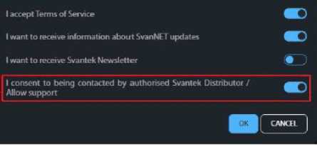
How do I enable support on my SvanNET project
Go to account settings and set all switches to ‘ON’
Are there any instruction resources for the use of SvanNET?
Videos can be seen above and also a range of tutorial videos are embedded within SvanNET
How can I configure multiple instruments on SvanNET?
Use ‘Clone Settings’ function on the platform to copy an instrument’s setup and send to other devices
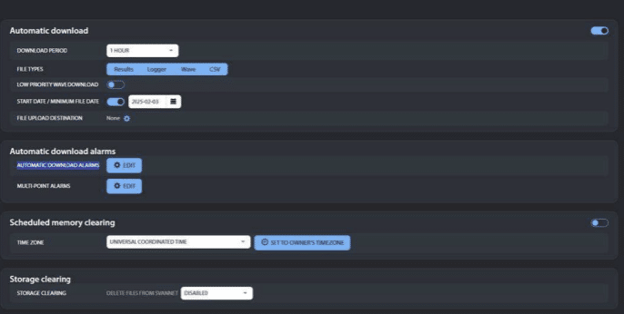
Setting alerts for dust monitors in SvanNET
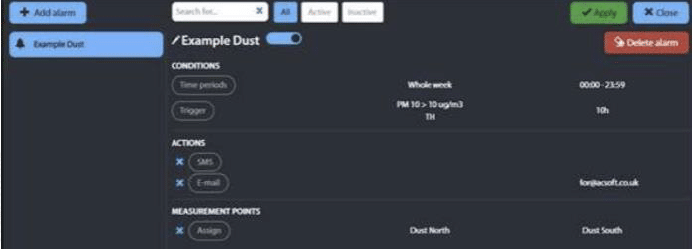
If you have administrator access to a project you can add email alerts for dust levels by setting an ‘automatic download alarm’ on it:

The below is an example if the basic settings for a dust alert 10 values of PM10 over 10 ug/m3 across a 10 hour period during the whole week.

This will be triggered when dust data is received by the project that meets the threshold criteria.
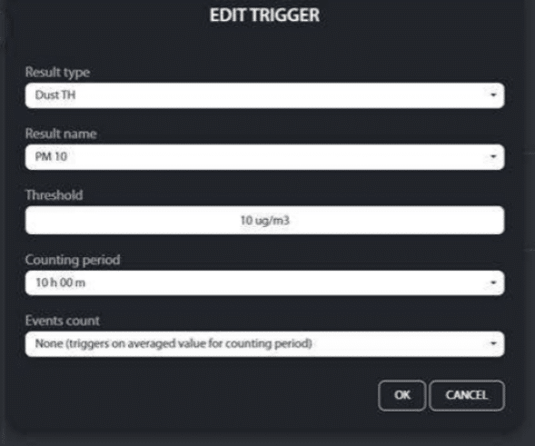
The settings for the trigger in this example are as follows:

Email is the mani means of sending free alerts to the appointed recipients, but SMS credits can be purchased to enable up to x1000 text messages to be sent in response to triggers.
This type of alert may be applied to measurements from any of the dust instrumentation that SvanNET supports.
Can other SIMs be used to connect the equipment to the cloud?
AcSoft’s supplied SIMs are preferred and supported, others not able to be supported outside of checking correct network configuration has been set on the instrument.
Verify that card is data enabled, and that network specific APN, username and password are set on instrument.How can I add alerts in SvanNET for Airly dust measurements?
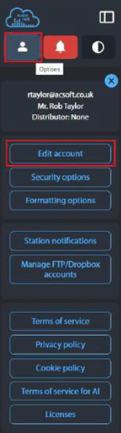
Go to the ‘Options’ menu at he top of the left-hand side bar then click on ‘edit account’ at the top of the list:

Scroll down to the bottom of this and where you will find 4 switches like the ones on my account pictured below – please ensure that the switch for ‘Enable support’ is shown in blue then click ‘ok’ to confirm:

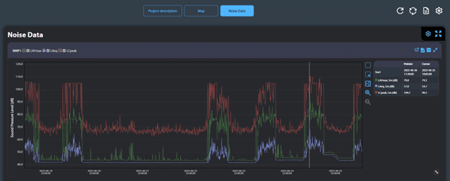
Setting SvanNET project report for 1 hour noise values
Generate a template for the data view
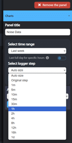
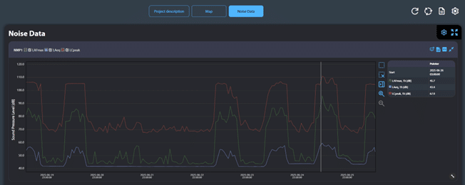
In this example, 1 week of noise data measured at the default 1 second logger step looks like he below chart when the ‘Auto size’ option selected on the panel:

Note that the ‘Auto size’ logger step is showing the data in this view ‘5m’ values:

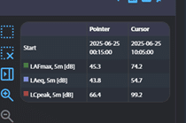
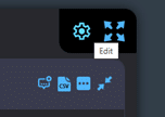
To recalculate the values for a specific logger step, go to ‘edit’ at the top of the panel as shown:

Then select the logger step, the values should be shown in and click ‘apply’:

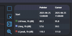
Having done this, the charts will now show the recalculated values:


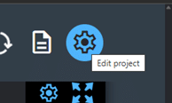
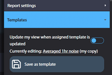
Next, save this revised view as a project template – go ‘edit project’ and select ‘save as template’ before adding a name and pressing ‘save as new’ – note the name you have given it – this will be used by SvanNET to generate the report:


Configure the Report
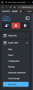
To configure a report, go to ‘reporting’ in the left-hand sidebar. Then select ‘configure automatic reports’/ ‘+Add new’
Add a title for the report and set a schedule and time period that the report should cover
Use the ‘template’ dropdown and select the template that shows the data as 1 hr values as created in part 1 above
Add the email addresses of recipients and set the format for the report to either pdf or docx. Click ‘save’ to store these settings
This new report will now appear in the list of automatic report configurations

The report will be automatically generated and sent to the appointed recipients at the point in time where the specified duration after the start time has passed, e.g. 7 days with the view formatted as per the template selected.
How can I delete projects from my SvanNET account?
To delete projects on SvanNET:
- Download all measurement data from the ‘cloud storage’ area on the project
- Go to ‘configuration’ from the left-hand sidebar, then click on the second ‘configuration’ box just to the right of it
- At the foot of the ‘modify project’ box that appears, click on the red ‘delete project’ button to remove it from your account
You also need to ensure that ‘Automatic Download’ is disabled on the project or you will see a warning that the deletion cannot be actioned.
Airly Set Up
Step 1: Complete the Airly Form and Receive Login Details
- Visit the Airly installation website
- Complete the form on the Airly installation website, ensuring you provide all necessary details
- After submitting the form, you will receive a response from Airly within 24 hours
- Once your form is approved, Airly will provide you with login details
Step 2: Request Installation ID Number From Airly Support
- Once you have received your login credentials, email [email protected] to request an installation ID number
- This installation ID will be necessary for setting up a measurement point on SvanNET
If you wish to make your data private, make sure to request this via email to Airly
Step 3: Create a Project in SvanNET Portal
- Log in to the SvanNET Portal
- Once logged in, go to the ‘project list’ section
- Click on ‘add new project’
- Provide a name for the project (e.g., “XXXX”) and enter the API Key in the box underneath ‘Airly data integration’
Step 4: Configure the Measurement Point in SvanNET
- Under the newly created project, select ‘modify measurement point’
- Fill in the following details for the measurement point:
- Point Name: Airly
- Point Short Name: (as needed)
- Point Description: (as needed)
- Geolocalisation
- Latitude: 52.218418
- Longitude: -0.478621
- Airly Installation ID: Enter the unique ID received from Airly support (e.g., 96512)
- Airly Results: Select the following data points you want to monitor
- PM1
- PM2.5
- PM10
- Pick Installation from Map: Choose the appropriate Airly installation
Step 5: Verify Data Transmission
- After successfully setting up the measurement point, you should start seeing data flow within 10-15 minutes
- You should then start to see data values appear
Dodecs
What is an omnidirectional sound source?
An omnidirectional sound source is a device that emits sound equally in all directions. Omnidirectional Sounds Sources, or Dodecs, are commonly used pieces of equipment in building acoustics, acoustic testing, such as measuring sound insulation and reverberation time
How compact are your omnidirectional sound sources?
All electronic circuits are built inside the spherical sound sources, making them highly compact and easy to transport.
The Lookline Dodecs also come with an in built pre-amp which saves time as it doesn’t need to be carried around.
How do I operate the omnidirectional sound source?
Simply connect it to a power source (battery or mains) and turn it on. A remote control allows you to manage all functions from a distance.
These functions consist of
- Play/stop noise playback
- Selection of 8 different noise types
- Adjustment of volume in 2 dB steps
- The choice of 4 calibrated power levels
- Storage of the last used noise and volume level
What types of noise are available?
White noise & Pink noise – Standard for acoustic testing
Fast white & Fast pink noise – More precise alternatives for real-time measurements
Sine sweep – Exponentially increasing frequency for reverberation time measurement (ISO 18233-2006)
Impulsive noise – Replicates a balloon burst or gunshot, useful for Schroeder method reverberation testing
Why is impulsive noise important?
It replaces traditional clappers and balloon bursts while providing a repeatable, omnidirectional, and extended frequency response.
How powerful are the sound sources?
We apply 150W RMS power for smaller models and 300W RMS for larger ones. This ensures high sound pressure levels while maintaining reliability and durability.
How do you ensure extended frequency response?
We use a range of different features to ensure extended frequency response. Our Dodecs are built with custom designed loudspeakers that compensate for frequency roll-off.
Our Dodecs also have a special magnet and coil design that enhances low frequency response.
They also use built-in electronic adjustments to balance the sound output across different frequencies.
What power options are available?
Battery & mains-powered models for flexibility
Lightweight batteries that provide over 1 hour of full-power operation
230V AC (115V AC for US versions) mains-powered models available
Do these units support external audio inputs?
Yes, all models include an auxiliary input for external signals. A Bluetooth input is also available as an optional feature.
IMMI
How to set up a indoor noise project
Receiver point calculation and results list
How to import geodata into IMMI
Setup a point source and grid calculation
SoundCheck
How to export SoundCheck sequences
How to use confidence limits
How to use sequence versioning
How to save virtual instruments files
Controlling audio device volume
How to protect sequences
How to check your calibration history
Organise data with the memory list
Using with accelerometers
SoundCheck signal generator secrets
Backing up important settings
Display secrets
General
Why am I getting LA,eq values below LA,90. Surely that's impossible?
No, it’s not impossible at all, and probably it is related to measuring low levels. By having a think about how statistical levels are calculated, all should become clear. Read more
What does IEC 61672 Cover?
IEC 61672 covers frequency response, linearity, directivity, detector, etc of the complete instrument, including effects of placing the instrument in a sound field.
Additionally, the instrument must meet tight requirements in ambient conditions – temperature, pressure, humidity, radiation, EMC (including any modems/radio elements) etc.
Sound level meter must meet ALL parts of 61672, not just some parts. For example, you CANNOT say “a microphone meets relevant parts of 61672”. It’s all or nothing.
It is easy to make an SLM work in the lab. NOT easy to make it work in the real world. You have to prove it.
BS 61672:2013 Edition
Class 1 and Class 2
Class 1 is required for legal metrology in environmental noise
Class 2 is sufficient for health & safetyBS61672:2013 is NOT the same as BS60804 which has four Types. This standard is obsolete.
Class 1 BS61672 is NOT the same as Type 1 BS60804
Sound level meter must meet ALL parts of 61672, not just some parts. For example, you CANNOT say “a microphone meets relevant parts of 61672”. It’s all or nothing.
Type approval not required in UK, but no-one in their right mind buys an instrument which has not been type approved elsewhere. Type approval is expensive. There are no short cuts. This affects the end-user price of the instrument. If it’s cheap, there’s a reason.
61672 part 3 covers the tests required for periodic calibration. Make sure your periodic calibration (UKAS or otherwise) covers ALL the tests in that standard, not just some.
It’s IMPOSSIBLE to claim compliance to BS 61672:2013 if all the required information is not provided in the manual for calibration or performance. If this information is not available, the instrument does not meet BS 61672, no ifs no buts. It is not possible to calibrate the instrument otherwise. This includes any correction for specific calibrators.
It’s not enough to say that your instrument meets most of 61672. It must meet all of it.
And it does matter. If any measurement results are presented for compliance with site limits, it is an easy matter for a lawyer to dig up any limitations of the measurement kit in relation to compliance with standards.
Environmental Monitoring
How do I calibrate my noise meter?
You will need to occasionally calibrate your microphone to be confident in its readings. You may already have an acoustic calibrator or pistonphone, or you will have purchased one with your meter. This will need to be professionally calibrated once per year with a certified calibration laboratory. If your acoustic calibrator has a valid certificate, you can calibrate the 97x meters in the Function > Calibration > Calibration by Measurement part of the meter’s menu. For the 958 series, usually Channel 4 is the sound channel. Enter the level of the tone being emitted from the calibrator (usually 94dB or 114dB – check the manual for the instrument) and place the calibrator firmly on the microphone. Take care not to carry this procedure out with high background noise.
If you need a formal instrument calibration carried out, which is recommended every 18-24months, please contact [email protected] with your requirements.
How do I calibrate a remote microphone system?
Condenser microphones are extremely stable and sensitive transducers when used in their normal operating conditions. When used for long-term noise monitoring, they can be exposed to more extreme environments (e.g. high temperatures, high windspeeds, moisture, etc) which may cause a change in sensitivity, and even damage. The nature of this type of monitoring often precludes a site visit to calibrate the microphone in the normal way, such as using a sound level calibrator or pistonphone mounted directly on the microphone capsule.
We therefore need a method of checking that all is well at the microphone end, so this describes three methods that can be used.
SV 307 Calibration
The SV 307 outdoor noise monitor is fitted with a MEMS microphone, for additional ruggedness and reliability. As such, none of the other two methods can be used. In the case of the SV 307, a small microspeaker is installed in the weather protection, which generates an acoustical signal which can be used for a calibration check.
The SV 307 also includes the possibility of sending alerts if the measured level is outside tolerances, or there is another issue with the patented microphone system.
In this way, you can be sure that measured results are valid.
Electrostatic Actuation
A more stable and repeatable calibration can be achieved by using an electrostatic actuator mounted on the microphone itself. This takes the form of a plate mounted very close to the microphone diaphragm, and normally replaces the standard protection grid. Some microphones incorporate the actuator in the weather protection system (e.g. rain cover). A variant is to electrically isolate the top plate of the standard microphone grille, so this doubles as the actuator (e.g. the MK255 capsule in the Svantek SV 200).
A signal (typically at 1kHz) is supplied by a generator, via a special amplifier, to create an electrostatic modulation of the microphone diaphragm. This is effectively an acoustic signal, so it checks not only the integrity of the microphone, but also the sensitivity. This is similar to the way microphones are calibrated in the laboratory.
This method therefore requires the generator and amplifier to drive the actuator, and is completely separate to the signal and powering chain of the microphone. Outdoor microphones such as the MTG WME960H have all the necessary electronics integrated, and the actuation can be triggered by a simple contact closure on a serial port for example. This method is used in many long-term monitoring systems, such as the Sinus Swing.
The SV 200 from Svantek is a complete outdoor noise analyser, and has the necessary system built-in. The electrostatic calibration can be triggered via a web page, either manually or automatically at predetermined intervals.
Although this method can be used as a ‘calibration’, the sensitivity of the system is not normally adjusted, but the levels logged to ensure accuracy of the results. Again, because the method requires external electronics and connections, it is not possible to do this via a single co-axial connection such as IEPE.
SysCheck
SysCheck or Charge Injection Calibration which simply injects an electrical signal into the microphone circuit, via the preamplifier, to check the signal path integrity. This includes the microphone capsule itself, which means that any change in the resulting measured signal can be used to deduce if the microphone capacitance has changed, which might be an indicator of damage (e.g. damage or corrosion on the diaphragm, or physical damage).
It’s important to note that this is not a ‘calibration’ as such, it is simply a means to check that nothing has changed out of tolerances, which can be preset by the measuring system. It is not a traceable acoustical signal.
In order to inject the signal, an additional connection is required on the preamplifier, and this is normally available via an industry standard 7-pin Lemo connector, used by many MTG power supplies. This method therefore precludes a simple co-axial connection to the microphone, such as IEPE, which is used solely to provide power to the preamplifier, and return the measured signal. Some front-ends have this calibration method built-in, such as Apollo from Sinus, where the Samurai software can provide the necessary signal on the correct pin of the Lemo connector.
Human Vibration Monitoring
What's all that IEPE, CCP stuff mean?
The output of the crystal is a charge, which requires a specialised charge amplifier, with extremely high input impedance, in order to drive our measuring system. These used to be separate boxes, with specialised low-noise cabling, but nowadays, the charge amplifier is built into the accelerometer itself, and this uses a ‘phantom’ powering system known as IEPE (integrated electronic piezo-electric), also known by a variety of proprietary names such as ICP®, CCP etc. At least IEPE is standardised! This means that long cables can be driven, and as long as your instrument can provide the powering, you should be in business. But always check that you have an IEPE accelerometer rather than a charge accelerometer first!
Due to being a capacitor, such accelerometers do not have a DC response, and will roll-off at low frequencies. Make sure you select one suitable for your task, if you want to measure down to 0.5Hz for example.How does a standard accelerometer work?
The majority of accelerometers for our applications are piezoelectric devices. A small piezoceramic crystal is sandwiched between the base and a seismic mass, so when the base is accelerated, the crystal is stressed, causing a proportional charge output. Because it is a simple mass/spring system, it will have a fundamental resonance – the crystal is very stiff, so this will be high, some kilohertz for most devices. Below that resonance, the response is virtually flat and linear, making an excellent transducer.
To make a sensitive accelerometer, make the mass and/or crystal bigger – but, this brings the resonance down, so there’s a trade-off to be made. Thankfully, most requirements for sensitive accelerometers are at low frequencies!How do you measure vibration?
Vibration transducers can be split basically into two types – accelerometers and geophones (or seismometers). Accelerometers have an output proportional to acceleration, and geophones have an output proportional to velocity. So how can both be used to measure vibration?
There’s a basic relationship between acceleration and velocity – the former being the rate of change, or the differential, of velocity. Therefore we can easily convert between the two by integrating an acceleration signal to yield a velocity signal. This is normally done in the time domain, using a filter (called an integrator), but it can also be done in the frequency domain by dividing an acceleration spectrum by 2πf, where f is the frequency. This effectively slopes the spectrum by -6dB/octave, so a velocity spectrum will appear to have a lot fewer high frequency componentsWhat's contact force and why do I need to measure it?
Contact force is a measurement of the amount of force between a user’s hand and the tool they’re using. The SV 103 personal vibration dosimeter and the SV 106D (when used with the SV 105AF transducer) are unique in that they measure contact force, which ensures any uncertainty of the measurement to be greatly reduced. You can choose to disregard any data where there is insufficient contact force.
The new dosemeter standard ISO8041-2, under preparation and until recently chaired by Paul Pitts of HSL, will specify a new class of instrument called a Personal Vibration Exposure Meter, which will require contact force measurement. Svantek have the only instruments which currently meets the draft standard, and the SV 103A and SV 106A are the only ones on the market for now.
Does the hand mounted vibration accelerometer comply with regulations?
There are two standards, ISO 8041:2017 and ISO 5349:2001 Parts 1 & 2
ISO 8041 covers the instrument specification, so things like frequency response, weighting filters, detector linearity, measurement parameters etc.
The SV 103 meets the standard.
ISO 5349 is a procedural standard, which tells you what you need (i.e. an instrument which meets ISO 8041), what to measure (e.g. AEQ, triaxial orientation of the hand, etc) and how to do the measurement (practical considerations, what to report, etc).
The SV 103A meets both parts of the standard.
The most common misinterpretation of ISO 5349 is that I have heard people saying you cannot use hand-held accelerometers for the measurement. It does not say this in the standard. It discusses both tool-mounted and hand mounted, and in fact, with many tools (e.g. sanders, polishers, planers etc) it is not possible to use a tool-mounted accelerometer.
Software
The software indicates my firmware is out of date, what do I do?
Contact [email protected] to request a firmware update and state the model and serial number of the meter. The appropriate firmware and instructions will be sent to you.
My meter won’t communicate with my computer?
To allow for communication between the software you use and the meter, you need to install the appropriate USB drivers for your Windows operating system. You can download the drivers from www.svantek.com Extract the zip file to a location on your hard-drive and install the drivers in the folder corresponding to your Windows operating system. Follow the on-screen instructions. You may need to install the drivers on other USB ports that you wish to use on the same computer.
L90 spectrum recalculation SvanPC++
The SV 307A is pattern evaluated (some use the term Type approved) to IEC 61672-2:2013 to Class 1 accuracy.
Please be aware that the calculation of statistical values is not standardised anywhere, and probably won’t be for some time. However, as long as the values which go into the calculation are from a quality instrument, you’re half way there.
How instruments on the market calculate statistical values is probably fairly consistent, but it’s the samples which go into the calculation which can give rise to different results. Sometimes it’s quite difficult to find out what values are being used, but it’s worth just looking at the different possibilities.
Most sound level meters will sample the raw acoustic wavefore at a high frequency, e.g. 48-50kHz. This is to ensure the Nyquist sampling criterion is met for the full measurement range.
From this stream of samples, it’s possible to calculate anything, so depending on the instrument, the simplest thing to do is calculate e.g. 5mm or 10ms short Leq values, and then calculate everything from that, e.g. F, S or period Leq. Note that this very short Leq value may be shorter than the time history step you can select in the instrument – it’s a background process.
These very short Leq values can be used to calculate the cumulative distribution of levels, but more of that later. Earlier statistical analysers used a longer sample rate of e.g. 100ms, simply because of available DSP power and memory at the time. This has found its way into some procedural standards, such as BS4142 which asks for a sample rate better than 100ms, and the IOA guidance on wind turbines for example. However, beyond that, there is no standardisation of the calculation.
The cumulative distribution of samples can be calculated from a time weighted detector or from Short Leq. If the short Leq is short enough, then you can also calculate F and S values too. This means that Ln can also be calculated from an F or S time-weighted stream! At Svantek, we offer both (choose the detector type in the measurement setup (EXP or LIN) but for most environmental noise, you won’t notice the difference.
So, what about this cumulative distribution? This is based on a set of samples (from our detector), and we create a set of bins with a class interval, e.g. 1dB. We then look at the sample, and put it in the relevant bin, e.g. if the sample is 45dB, we typically put it in the bin (45-46dB). Of course, these days we have more resolution, so typically the class interval is 0.1dB, over the linearity range of the instrument (e.g. 0.1dB resolution over a 80dB linearity range will give 800 bins).
From this cumulative distribution, we can then start to ask questions, such as what is the level exceeded for n% of the time, e.g. what is the level exceeded for 90% of the time, or L90. And L90 is often used as an indicator of background noise of course.
So how accurate is this value of Ln? Well, it depends on the statistical confidence we have in the distribution. If we don’t have many samples, then we are not so confident. 1000 samples will give us a ‘better’ confidence than 10 samples. There are some other things that affect confidence but I remember doing an IOA paper in the mists of time about the effect of sampling accuracy on Ln confidence, but I think it’s written in Freelance Graphics which was two iterations before Powerpoint became a thing!
Anyway, it only becomes a problem when we want values of Ln in short time periods, such as 1 minute (normally we would calculate hourly Ln values for example).
This is not a problem if we calculate the Ln in the instrument, as we probably have 100 samples a second going into the calculation, so for one minute, I have 6000 samples to play with. However, if I want to calculate a one-minute Ln from a stored time history file (such as that calculated in the SvanPC++ software), then we’re still going to have to have enough samples to be confident in the result. We typically recommend 100ms sampling for post-processing, which in this case will give you 600 samples to base your calculation on (I think in my paper, I concluded a minimum of around 800 samples gave a consistent result, but it was a long time ago!).
For the same statistical confidence if you only have one-minute values, then you’ll need to use 10 hours of data to get your Ln value! Clearly that doesn’t make sense, but the nature of software is to allow you to do it.
Hopefully, you can see that it’s possible to calculate Ln however you want, but it’s important to pay attention to the statistical accuracy
If you thought Ln calculation was tricky, why not introduce Ln values in 1/n octave bands? These days, it’s a trivial DSP burden, so functions like this are available in instruments as well as post-processing software.
I think this stemmed from the idea that if broad-band Ln is an indicator of background noise, then an Ln spectrum in octave bands is an indicator of background spectrum.
This is not true. It may be sort of true for certain types of signals, but you would have to know the signal in advance.
This is the Wild West of noise assessment, and I would recommend a quick read of a paper a wrote a few years ago in the IOA Bulletin.
Every frequency band in the spectrum is independent of the next one, so the spectrum doesn’t really exist in real life.
I really would not recommend using Ln values in 1/n octave bands, unless you have absolute confidence in what the calculation is telling you, but that’s just me!
Top Tips
- When calculating statistics using post-processing, make sure you have enough samples to be confident of the result
- Be doubly careful if calculating statistics of spectral values
- Statistical calculations are not standardised so know what you are doing
- Avoid calculating statistics over short periods
- Don’t calculate anything just because you can
Personal Noise Dosimetry
Why would I want octave band filters on a noise dosimeter?
The answer is simple really – if you want to correctly select hearing protection for your workers.
There are a number of ways to take measurements to help select hearing protection including C-A and HML measurements but these are all compromises compared to taking correct octave band measurements. 1/1 octave analysis is an option for the SV 104A noise dosimeter.
Ground Vibration Monitoring
How do I calibrate my vibration meter?
Similar to your noise meter, your vibration meter will need to have a formal calibration carried out every 18-24 months – please contact [email protected] It is also possible to carry out a field calibration with the SV 111 or SV 110 vibration calibrator depending on the type of accelerometer you are using. The latest version of ISO8041 specifies field calibration procedures.
How big a USB memory stick can I use with the USB host facility of 95x series instruments?
In general, the larger the USB memory, the larger the current requirements, and the slower the speed of the memory. The Svan 95x are low power devices, so have an (intentionally) limited supply of power to the USB host. Therefore, we recommend that the maximum memory size is 4GB, as this provides the best compromise between power, speed and capacity. Larger memory sizes may work perfectly well, but we can’t guarantee it.
Also, we recommend good brands such as Kingston, rather than supermarket own-brand.
So why should I choose the SVAN 958A over the SV 106A?
If you want to measure noise, have remote communications and measure dominant frequency, then SVAN 958A is the best choice.
Does the SV 106A do FFT?
No, but 1/1 and 1/3 octave options are available.
Does the SV 106A do PPV and VDV at the same time?
Yes, each channel has two profiles, so you can measure unweighted PPV and weighted VDV at the same time.
What about the SV 106A? Can I use that for ground vibration?
Yes, the 106A is a six channel instrument so two triaxial locations can be measured.
Can the SVAN 958A measure Vibration Criteria?
Yes, with the normal SV84(SV207B) triaxial accelerometer, and 1/3 octaves installed, you can measure VC-A to VC-D, but for measurements to VC-E and NIST-A, we recommend using a 10V/g accelerometer instead, as that gives you more headroom over the noise floor. Typically, three accelerometers are mounted orthogonally in an SA217 block – ask for details.
Can the SVAN 958A measure according to the criteria in BS7385?
Yes, if the FFT option is installed, then PPV and dominant frequency can be stored and displayed correctly in SvanPC++ with the threshold criteria.
Can I trigger from a vibration event and send an email/SMS?
Yes, if the 958A is equipped with a serial interface and modem (options), then two trigger levels are available on each channel, typically used for warning and alarm levels.
Can I measure noise at the same time as triaxial vibration on the SVAN 958A?
Yes – we use channels 1-3 for vibration, and channel 4 can be used for noise measurements to Class 1 accuracy. Measurements include Leq and Ln as standard, and spectra (if option installed).
Can I capture the event signal file on the SVAN 958A?
Yes, if the WAV option is installed, the ground vibration firmware will also capture the signal file to a USB memory stick.
Can I measure dominant frequency to BS7385 on the SVAN 958A?
Yes, if FFT is installed, the ground vibration firmware allows storage of dominant frequency. This is preferred over zero-crossing methods, as it reduces errors caused by complex time waveforms.
Can I measure VDV and PPV at the same time as 1/3 octaves?
In the special ground vibration firmware, 1/3 octave analysis is possible at the same time as PPV and VDV, FFT (option) can also be used.
Can I measure VDV and PPV at the same time?
Yes, in the special ground vibration firmware (included as standard), you can measure both at the same time, although ask yourself why you need to do this – normally VDV is for vibration nuisance/disturbance and PPV is for building damage, so they tend to be measured in different places.
Can I measure 1/3 octaves at the same time as PPV?
Yes, but you need the 1/3 octave option installed.
Can I measure 1/3 octaves at the same time as VDV?
Yes, but you need the 1/3 octave option installed.
Can I measure a VDV time history on the SVAN 958A?
Yes, you can log individual VDV values with time, e.g. for train pass-bys etc. They can then be accumulated in the SvanPC++ software. Periodic (e.g. hourly) VDV values can be stored at the same time
Can the SVAN 958A measure VDV?
Yes, it measures VDV according to BS6472, and you can select Wd weighting for the horizontal axes and Wb for the vertical axis. Wg is also available for backwards compatibility with the old version of the standard.
Can the SVAN 958A measure PPV?
Yes, it measures PPV directly, with selectable high pass filters of 1, 3 and 10Hz. We recommend 3Hz filter for measurements to BS7385
Calibration
What is the correction factor in the calibration menu and does it vary?
All sound level meters will be designed electrically for a nominal microphone sensitivity. This will depend on the microphone type – e.g. an MTG MK255 microphone will have a nominal sensitivity of 50mV/Pa, and a 7052E microphone will have a nominal sensitivity of 31.6mV/Pa.
In practice, the sensitivity of a supplied microphone will differ from nominal, due to manufacturing tolerance. You will see its actual sensitivity on the calibration chart. Note that this sensitivity is ‘open circuit’ so it does not take into account the preamplifier/cable gain or otherwise of the meter.
Therefore, if the microphone has a lower sensitivity than nominal, then the meter has to compensate for this, by using a correction factor, C. C will be positive for a less sensitive microphone, and negative for the more sensitive one.
The value of C is generally stable between one calibration and the next, but depends on ambient conditions. You can check this in the Calibration History. If it varies a lot between calibrations, then you need to check the microphone or calibrator for damage, or another fault.
When I have done my calibration, why do I get a different result when I measure with the calibrator on the microphone?
During the calibration process, the instrument is set to C-weighting, and all other filters are switched off, regardless of the setup of the meter prior to calibration.
Once you have exited the calibration process, you enter the measurement mode, and it’s possible you may get a different result. This is because you may be measuring with a different frequency weighting, or you may have selected an outdoor correction or windscreen correction. Also, the instrument may have a filter which corrects for reflections around the case of the instrument itself. As the calibration is a calibration of sound pressure, expect to get different results when the instrument is used in free field.
Knowledge Hub
Introducing Our New Calibration Portal
March 25, 2026
We are excited to announce the launch of our brand new calibration portal, designed to make accessing and managing your calibration certificates easier than ever before. Our portal provides a secure, central location for all certificates, giving you instant access whenever you need them. Whether you are preparing for an…
A Deep Dive Into the SV 106D
February 18, 2026
Managing vibration exposure is a core part of controlling HAVS and whole-body vibration risks. But how does one do this accurately and consistently? Well, with a human vibration monitor. The SV 106D gives health and safety professionals a reliable way to measure, assess, and manage vibration exposure in line with…
Introducing the CRY3213 Ruggedised Measurement Microphone, Designed for the Harshest Environments
February 6, 2026
We are pleased to announce the arrival of the CRY3213 NVH measurement microphone from Crysound, designed specifically for accurate and repeatable measurements in automotive, aerospace and engineering noise vibration harshness testing. Developed for engineers, the CRY3213 offers a practical and cost effective option for both new and existing test setups.…
Vibration monitoring Just Got A Little Bit Smaller: Meet The SV 804
January 12, 2026
Introducing the new SV 804 wireless triaxial vibration monitor from Svantek, designed for construction, infrastructure, environmental, mining and more monitoring applications. What Are The Key Features of the SV 804? Compact, Direct Mount Design The SV 804 has a significantly more compact enclosure, weighing just 1.7kg! The monitor is purpose…