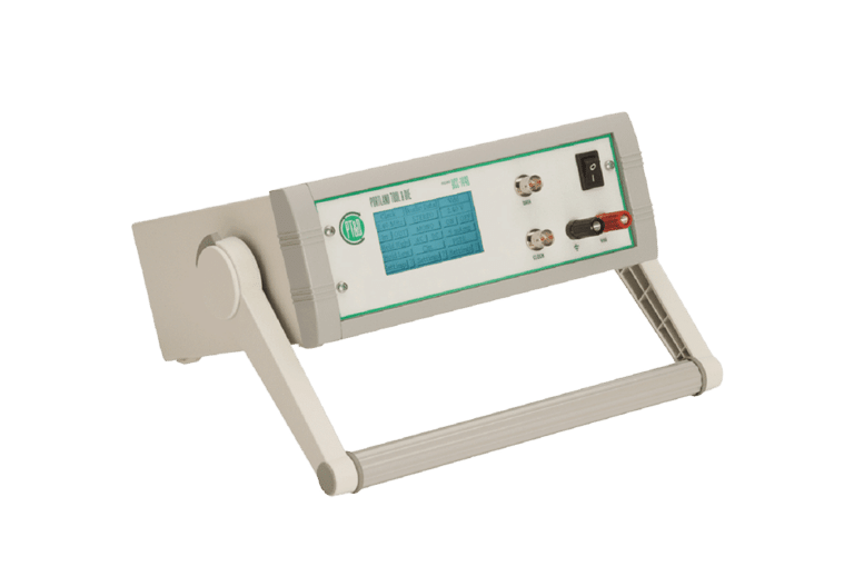
The DCC-1448 Research Grade MEMS Interface
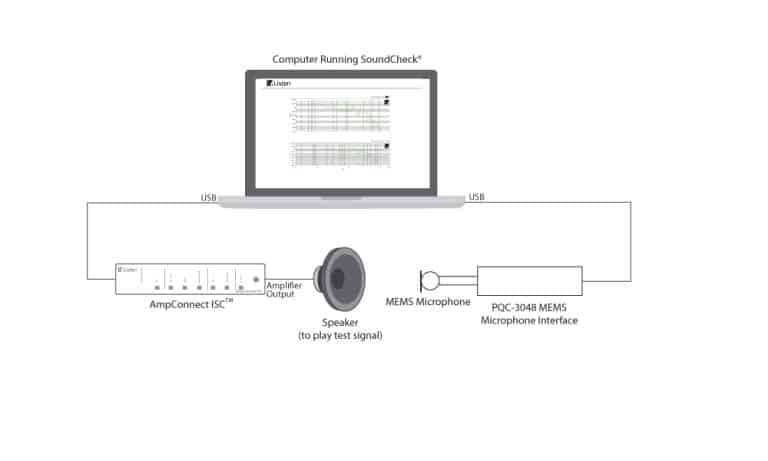
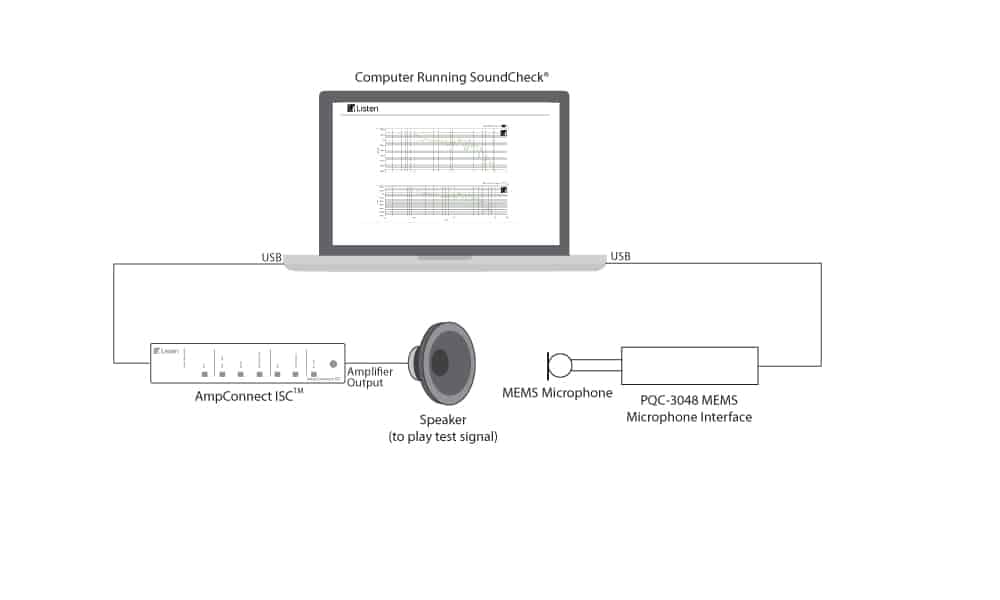
The DCC-1448 is a research-grade interface for measuring and characterising MEMS (Micro-Electro-Mechanical-Systems) microphones and other devices with a 1-bit PDM (Pulse Density Modulation) output. Used in conjunction with an audio test system such as SoundCheck®, it forms a complete solution for the quantitative test and measurement of MEMS digital microphones.

Interested
For more information on The DCC-1448 Research Grade MEMS Interface or to request a quote, contact our team now:
In addition to converting the MEMS microphone’s 1-bit PDM output to a 24-bit, 48kHz PCM signal, it also includes features to measure characteristics unique to MEMS microphones. These include a programmable clock for measuring performance relative to sample rate, a programmable power supply for measuring performance relative to supply voltage and a power supply rejection impairment generator for measuring power supply rejection ratio (PSRR). The instrument is acoustically silent and can therefore be used inside an anechoic chamber, a useful feature since MEMS microphones can only drive a short cable.
Features include:
- Control and configuration within SoundCheck, via USB, or using the front panel
- Straightforward operation – the data input, clock, Vdd, and ground interface are on the front panel, and the rear panel contains USB and SPIDIF interfaces for connection to the computer’s audio interface
- Simultaneous SPDIF and USB digital audio output are compatible with most test equipment with digital audio inputs and both Mac and Windows computers.
- Programmable clock typically operates as the master, but can also operate in slave mode (e.g. for measuring the performance of a PDM signal generator, synching multiple microphones in an array, or where the use of an external clock is preferred)
- Conversion occurs entirely in the digital domain
- Can interface with two microphones simultaneously. This is useful for testing the finished product that contains multiple microphones or for characterizing matched pairs. When using two microphones all connections are shared, including the data line; one microphone transmits data on the rising edge of the clock pulse and the other on the falling edge of the clock pulse. Internally to the instrument, the decoded data is sent to the left and right channels of the SPDIF and USB outputs. When using two microphones the L/R selection line of one microphone is tied to ground and the other is tied to Vdd.
PDM Data Input
0.5 to 4 MHz sample rate
Mono or Stereo multiplex
1.5 to 5.5 V logic level
Selectable 5, 50, 100, 200, or 400 pF input capacitance
Selectable open or closed circuit
BNC Connector
PCM Data Output
24 bit, 48 kHz sample rate
SPDIF/AES3 BNC
USB Audio – Windows and Mac compatible
Clock
Selectable clock master or slave
1 to 4 Mhz
Selectable 1.4 to 5.5 V logic level
Clock modes: In, Out, Hold High, Hold Low
BNC Connector
Vdd DC Power Supply
0 to 5.5 V DC
10 mAmp current limit
Selectable power supply rejection impairment waveform generator
Control Interface
Touchscreen Display
USB
Windows command line interface
Physical
Dimensions: 86 (H) x 271(W) x 211 mm (D)
Weight: 1.6 kg
Power: 12 VDC, 24W power input (Supplied with universal 100 to 240 VAC, 50 to 60 Hz power supply)
SHARE THIS
Related Products
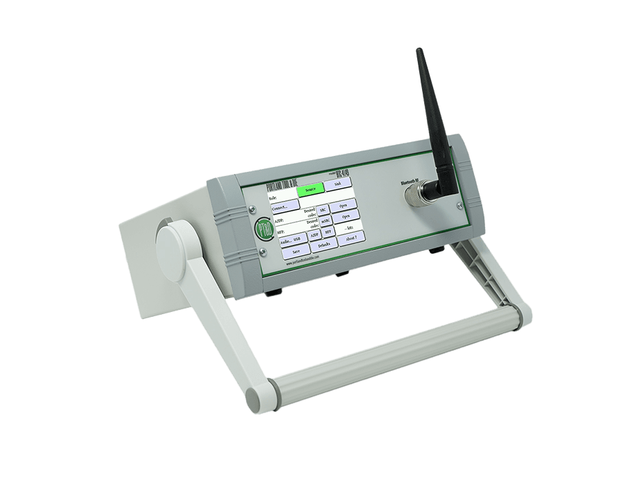
BTC-4149 and BQC-4149 Bluetooth Measurement Interfaces
Listen offers 2 Bluetooth interfaces from Portland Tool & Die, the laboratory-grade BTC-4149 and the low cost BQC-4149 for production line use. These are ideal…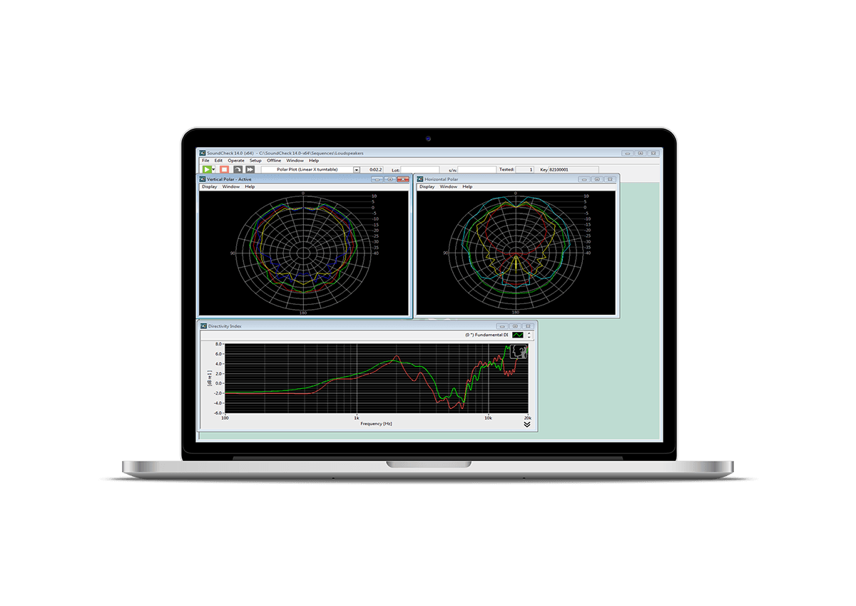
Contact Us
To contact us regarding the
The DCC-1448 Research Grade MEMS Interface
Complete your details below:
Request a quote
To request a quote for the
The DCC-1448 Research Grade MEMS Interface
Complete your details below: